Beam Elements: Taper Rules
Description
Beam cross sections can be tapered by applying the Beam Taper attribute to individual beam elements (see Beam Attributes: Taper). The section can be tapered in both directions with different taper ratios at each end.
Tapering BXS Sections
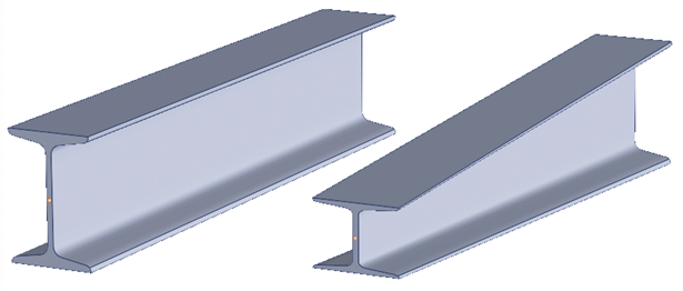
When a BXS is tapered, the entire cross section geometry is scaled by the taper attribute. In the example illustrated in the following image, not only the depth of the section, but also the thickness of the flanges are reduced at the tapered end. The thickness of the web remains unchanged in this case because the taper has only been applied in the local y direction.

Tapering BGL Sections
Beam cross sections that come from the Beam Geometry Library (BGL) are treated the same as a BXS for the purpose of taper. That is, the entire section is scaled. In the following image, the tapered beam has a short web at the tapered end, as well as thinner flanges.
Tapering Standard and BSL Sections
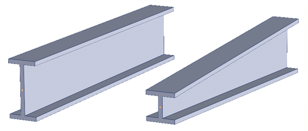
Standard beam cross sections and beam cross sections from the Beam Section Library (BSL) are tapered according to certain rules that generally apply the tapering to the flanges and webs, without affecting thicknesses. In the example illustrated in the following image, the tapered beam has a short web at the tapered end, but the thickness of the flange is the same as in the untapered beam.
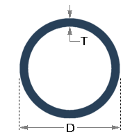
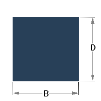
The following table summarises the tapering rules employed by Strand7 for the standard section shapes.
|
Cross Section |
Taper x |
Taper y |
Unchanged |

|
D | D | |
|
D | D | T |
|
B | D | |
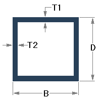
|
B | D | T1, T2 |
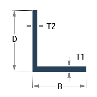
|
B | D | T1, T2 |
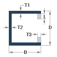
|
B | D, L | T1, T2, T3 |
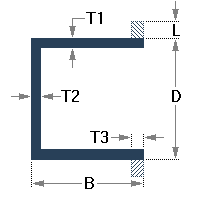
|
B | D, L | T1, T2, T3 |
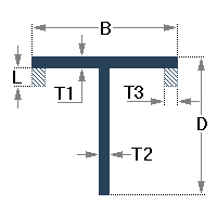
|
B | D, L | T1, T2, T3 |

|
B1, B2 | D | T1, T2, T3 |

|
B1, B2 | D | T1, T2, T3 |
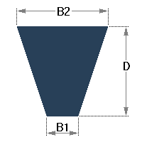
|
B1, B2 | D | |
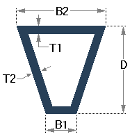
|
B1, B2 | D | T1 |
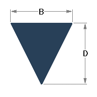
|
B | D | |

|
B | D | T1, T2 |
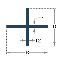
|
B | D | T1, T2 |
See Also