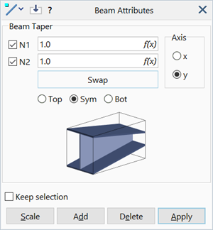
Beam Attributes: Taper

Description
Assigns taper ratios along the local x and y axes of selected beam elements.
Different taper ratios may be assigned along each local axis.
Beam taper attributes are independent of load and freedom cases, and are only applicable to beam and truss type beam elements that have cross section geometry defined. The way the cross section is tapered depends on the cross section type, as described in Beam Elements: Taper Rules.
Dialog
Tapers N1 / N2
The cross section scaling factors at the beam ends.
Values must be greater than zero and can be greater than one.
Swap
Swaps the values of N1 and N2.
Axis
Local beam axis in which the taper will be defined.
A beam element may be tapered at one or both ends, and along one axis or both axes.
Taper direction
The beam can be tapered such that it is:
- aligned with the top of the selected local axis (Taper = Top),
- symmetric about the selected local axis (Taper = Sym), or
- aligned with the bottom of the selected local axis (Taper = Bot).
The Top and Bot options do not offset the position of the beam relative to the nodes; the node positions at the ends are always located at the centroid of the tapered (i.e., scaled) section. Therefore, if a tapered beam need to be interconnected with untapered beams, node positions may need to be adjusted (so that the node remains at the centroid of the tapered section while maintaining the desired geometric continuity).
The following example illustrates how the node positions need to be adjusted to define a 3-segment I-beam with a flat top-flange.
The initial mesh consists of three untapered beams, each 1000 mm long. The end segments have a section depth dimension of 300 mm, while the middle segment has a section depth of 120 mm; both of these sections are defined in the beam property data. The two end segments are to be tapered to connect with the middle segment exactly, while keeping the top flange of all three segments flat and in line with the ends of the untapered sections.

To produce the depth of 120 mm, the taper ratio at the tapered ends is 120/300 = 0.4. If this taper ratio is applied to the end beams with the Sym option, we produce the following geometry:

This is the symmetric case, which does not keep the top flange flat. We can see this because the angle between the web and the flange and the ends is not 90 deg.
To obtain the required 90 deg angle, we select the Top option. This produces the following geometry, with the correct shape for the tapered beams (i.e., 90 deg angle at the top), but with the ends at the wrong location.

To line up the top flanges of all three segments, the middle segment needs to be moved up. The amount of vertical node movement required is:
Using Move Tools: by Increment, the nodes are moved up to produce the required geometry.

Common Controls
See Also