Entities: Geometry Entities
Description
Geometry entities are vertices, edges and faces that define geometry and topology of the model. They are not finite elements in themselves, but are used to create finite elements by automeshing or other methods. Geometry entities are usually imported from a CAD file (see Utility: Import) or manually generated using Geometry Tools.
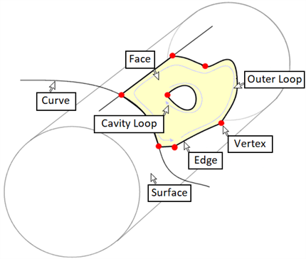
Strand7 represents the three-dimensional domain of geometry objects in a manner analogous to Boundary Representation (Brep) solid modelling. In this representation, any geometric object can be represented by a collection of faces requiring the definition of the following geometric and topological entities:

-
Face
A face is a topological entity consisting of one or more loops located on a three-dimensional surface. The face defines a region of finite area, on a surface that may be of either finite area (e.g., a sphere) or infinite area (e.g., an unbounded plane). Each face contains either one or two bounding or outer loops: non-periodic faces contain one outer loop; periodic faces, such as could be used to define a simple cylinder without any seam, may contain two outer loops. Faces can contain any number of additional cavity loops. A cavity loop defines a region on the face where material has been removed (e.g., a hole). Faces may be assigned attributes such as pressure. These attributes are then automatically assigned to elements upon automeshing.
-
Loop
A loop is a topological entity consisting of a collection of connected edges. In a well-defined loop, the end of the last edge is coincident with the start of the first edge.
-
Edge
An edge is a topological entity consisting of one or more connected curves. Associated with each edge are a start vertex and an end vertex. For single edges that form a closed loop, the start vertex is the same as the end vertex. Edges may be assigned attributes (e.g., shear stress). These attributes are then automatically assigned to elements upon automeshing.
-
Curve
A curve is a geometric entity defining a line in 3D space. A curve may be an analytical curve (ellipse, straight line, etc.) or a spline curve. When a curve is associated with a surface via the edge to loop to face hierarchy, the curve may be defined with reference to 3D global space, or with reference to the local (u,v) parametric space on the surface. An example of the former could be a line segment between two points in 3D space that also lies on a specified plane in 3D space. An example of the latter could be a circular segment that lies on a cylindrical surface but is defined in terms of (theta, z) coordinates on the cylinder.
-
Vertex
A vertex is a geometric entity defining a point in 3D space. Vertex points are used to define the ends (start and end points) of edges. A correctly defined vertex must lie on the curve that is referenced by the edge that references the vertex. Vertices may be assigned attributes (e.g., a point force). These attributes are then automatically assigned to the node generated at the vertex position upon meshing.
-
Surface
A surface is a geometric entity that defines the finite or infinite domain on which a face lies. Surfaces can be either analytical surfaces (planes, cones, spheres or torii) or they can be spline surfaces. Analytical surfaces require a small amount of data to define them. For example, a plane can be defined by a vector representing the surface normal together with a point that lies on that plane. Spline surfaces, particularly complex curved surfaces defined by many control points, can require large amounts of data.
See Also