LAYOUTS: Laminates
Description
Defines the layup of laminates, which can be assigned to laminate plate elements, and generates the material matrices and equivalent engineering properties.
Up to 300 plies may define a laminate. Each ply is defined by the following data:
- its fibre direction with respect to the element reference (i.e., the local x axis of the plate element);
- the ply material property data (LAYOUTS: Plies); and
- its thickness, which can be explicitly set or taken from the ply material data.
The first ply in the laminate is located on the -z surface of the plate element, whilst the last ply is located on the +z surface.
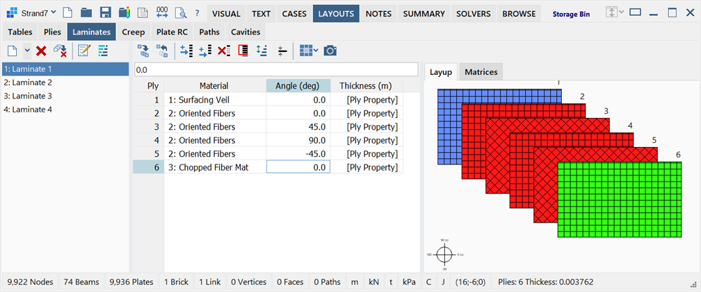
The LAYOUTS: Laminates sub-tab is divided into three panes: laminate list on the left, ply layup grid in the middle, and graphical representation on the right.
Laminate List
Situated on the left of the window, it lists the available laminate layouts.
Ply Layup Grid
Situated in the middle of the window, the grid displays the layup of plies, their alignment angles and thickness.
Ply
Displays the ply layer order from the bottom (Ply 1) to the top of the laminate. The values in this column are automatically updated as the number of plies in the laminate is changed.
Material
Displays the selected ply property number and names. These can be selected via the dropdown list of available ply properties in the grid.
The <Undefined ply> property can be used for any ply. Undefined plies are ignored for the purpose of material matrix and results calculations, but they still occupy a ply number in the laminate. They can therefore be used as place holders. This enables adjacent laminates to maintain continuous ply numbers even if one of the laminates has a ply drop-off.
Angle
Specifies the angle, in degrees, between the 1-axis direction of the ply and the local x axis direction of the plate element.
An angle of zero aligns the ply 1-axis to the local x axis of the plate element, while an angle of 90 degrees aligns the ply 1-axis is to the local y axis of the plate element.
Thickness
Specifies the thickness of the ply in the length units of the model.
If this is set to zero, the thickness of ply is retrieved from its ply property definition (LAYOUTS: Plies). In that case, the [Ply Property] label is shown in place of a numeric thickness value in the grid.
Graphical Representation and Properties Pane
Situated on the right of the window, the pane consists of two tabs:
-
Layup
Displays an illustration of the laminate stack composition. Each ply is rendered in the colour of the respective ply property, and its position in the stack is labelled. The angle of the ply 1-axis is indicated by the angle of the cross-hatching, which is based upon the Weave setting in the ply property definition.
-
Matrices
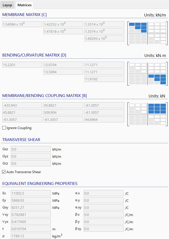
Displays the material matrices and the equivalent engineering properties of the laminate.
[C] [D] [B] MATRICES
The element material matrix of the laminate for membrane, bending and membrane/bending coupling.
-
Ignore Coupling
If set, the membrane/coupling matrix [B] is excluded from the element stiffness matrix for analysis (it is effectively set to zero).
TRANSVERSE SHEAR
Three coefficients (including a coupling term Gcz) defining the relationship between transverse shear stress and transverse shear strain. Refer to Mindlin-Reissner Hypothesis for Thick Plates literature for more information.
-
Auto Transverse Shear
If set, and the transverse moduli of all the plies in the stack are defined, Strand7 will automatically calculate the effective transverse shear moduli of the laminate. If not set, the coefficients of the transverse shear matrix (Gxz, Gyz, Gcz) may be entered directly.
EQUIVALENT ENGINEERING PROPERTIES
Effective properties calculated from the laminate layup.
- Ex, Ey : Effective elastic moduli in the laminate local axes.
- Gxy : Effective in-plane shear modulus.
- νxy, νyx : Effective Poisson's ratios.
- t : Total laminate thickness (a summation of the individual ply thicknesses).
- ρ : Effective laminate mass density.
- αx, αy, αxy : Thermal expansion coefficients for in-plane strain.
- βx, βy, βxy : Thermal expansion coefficients for out-of-plane curvature.
-
Toolbar Functions
In addition to the common controls, the following functions are available:
Insert row
Inserts a new row in the grid before the highlighted cell. A new ply is inserted into the laminate, initialised as an <Undefined ply>.
Add row
Adds a new row of data point to the end of the list.
Adds a new row to the end of the grid. A new ply is added to the bottom of the laminate, initialised as an <Undefined ply>.
Delete selected rows
Deletes plies by deleting the highlighted rows in the grid.
Reset the number of rows
Opens the Reset Rows dialog in which the new number of plies for the current laminate can be specified.
Invert selected plies
Inverts a set of selected consecutive plies.
This function is typically used to define symmetric laminates by copying and pasting one half of the already defined layup, and then inverting it.
Retrieve thickness from ply property
Retrieves the thickness values from the ply property data (LAYOUTS: Plies) based on the current ply material for a range of rows selected in the grid. The ply property thickness then overwrites the current thickness of the ply.
This function is generally not necessary since by setting the ply thickness to zero, the thickness in the ply property is used (indicates as [Ply Property] in the Thickness column of the grid).
Assign laminate to plate property
Two options are available for assigning the laminate to a plate property, avoiding the need to retrieve the laminate definition from the respective property dialog later.
-
Assign to existing plate property
Opens the Assign Laminate Layout to Plate Property dialog to enable the assignment of the current laminate layout to selected properties.
-
Assign to new plate property
Creates a new property and assigns the current laminate layout to the new plate property.
See Laminates: Assign Laminate Layout to Property.
Copy graphic to clipboard
Copies the graphical representation of the laminate to the clipboard as an image.
Right-click Functions
Right-clicking the spreadsheet area opens a popup menu and provides additional functions. See Strand7 Interface: Right-click Functions.
See Also