SOLVERS Parameters: SUB-STEPPING (Static)
Description
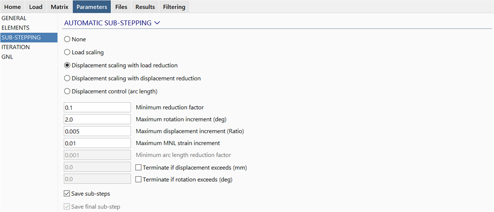
Configures automatic sub-stepping of the Nonlinear Static solver.
Automatic sub-stepping is used for improving the convergence of difficult nonlinear models, and/or to automatically produce result steps in nonlinear solutions without specifying every individual step via SOLVERS: Load (Nonlinear Static).
None
Automatic sub-stepping is not used.
Load scaling
When sub-stepping is triggered using the Load scaling option, the difference in the load factors between the current and the previous load steps is halved, and the load step is restarted as a sub-step using these factors. That is,
 .
.
If convergence cannot be achieved in the sub-step, the difference is halved again and the load step is again restarted.
For example, consider the load incrementation table below, set up via SOLVERS: Load (Nonlinear Static).
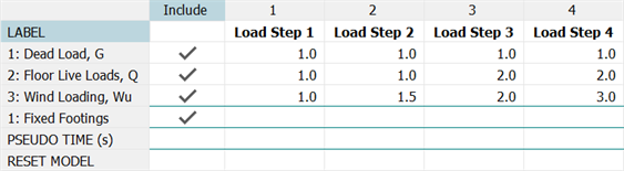
If convergence cannot be achieved at load step 2, the difference in the load factors for the three load cases is halved. This means that the load factor in load case 3 will now be 1.0 + (1.5-1.0)/2 = 1.25. It also means that for load cases where the load factors in two successive load steps are the same value, the sub-stepping operation cannot change the applied load for those load cases.
If convergence cannot be achieved in this sub step, the factor in load case 3 will become 1.125. Reductions for non-converging sub-steps will continue to be applied until the Minimum reduction factor is reached. This factor controls how small the sub-steps can get. If the minimum reduction factor has been reached, and convergence still cannot be achieved, the results of the unconverged sub-step are accepted and the solver continues on to the next sub-step.
If a sub-step converges, the load factors in the following sub-step are scaled up. The next factor is calculated as the current factor plus twice the difference between the current and the previous factors. That is,
 .
.
If this value exceeds the value defined in the load incrementation table , the value in the table is used.
Displacement control via enforced displacements, and constant terms in multi-point constraints, are also scaled by the sub-step scaling factor to keep all the loading and enforced displacements in the sub-step proportional to those specified in the load incrementation table.
Sub-stepping by Load scaling can be triggered by any of the following events:
-
The solution does not converge within the set number of iterations and Allow solver to add iterations in SOLVERS Parameters: ITERATION (Structural) is not set.
-
The solution begins to diverge when the set number of iterations has already been exceeded and continuing iteration has been allowed by the Allow solver to add iterations option.
-
The global matrix is singular.
-
The Maximum MNL strain increment is exceeded at any nonlinear material beam.
Displacement scaling with load reduction
In this option, sub-stepping is triggered in exactly the same way as for the Load scaling option, with reductions for non-converging sub-steps continuing until the Minimum reduction factor is reached, if the non-convergence persists.
However, the vector of iterative displacements produced at every iteration of the solution procedure is controlled to avoid large relative movements during the process. This helps to smooth out large load imbalance fluctuations that can sometimes destabilise the iteration process.
The entire vector of displacements and rotations produced in every iteration is scaled down if any node exceeds the Maximum displacement increment (Ratio) or the Maximum rotation increment (deg).
- The Maximum displacement increment (Ratio) is exceeded if any iterative displacement divided by the bounding box dimensions of the model exceeds the set ratio.
- The Maximum rotation increment (deg) is exceeded if any iterative rotation exceeds the set rotation.
In many structures, particularly stiffening structures, the Displacement scaling with load reduction option works very well as it allows the structure to develop the necessary stiffness and stability to eventually equilibrate the total externally applied loads.
Displacement scaling with displacement reduction
This option is similar to the Displacement scaling with load reduction in that it controls the iterative displacements to ensure that they are no larger than the Maximum displacement increment (Ratio) and Maximum rotation increment (deg) settings.
However, if convergence cannot be achieved within the set number of iterations, or according to the Allow solver to add iterations parameter, the solution does not sub-step. Instead, the Maximum displacement increment (Ratio) and Maximum rotation increment (deg) settings are reduced and the load step starts again. Reductions for non-converging steps can continue until the Minimum reduction factor is reached.
This method is useful in situations where convergence of the majority of load steps does not require an excessively small Maximum displacement increment (Ratio) or Maximum rotation increment (deg). For the load steps that require it, the solver automatically reduces the values.
Displacement control (arc length)
Unlike the previous three options, which are primarily designed to improve the convergence of difficult nonlinear problems, the Displacement control (arc length) option is very useful not only for difficult nonlinear problems, but also to automatically set up and save load steps without having to define them all via SOLVERS: Load (Nonlinear Static).
This option also uses the Maximum displacement increment (Ratio) and the Maximum rotation increment (deg) settings to control the maximum displacement and rotation. However, this control is not applied to the iteration but to the result step or sub-step; that is, to the total increment of displacement and rotation from the last saved sub-step to the current one.
When using the Displacement control (arc length) option, sub-stepping occurs independently of the convergence of a load step; a load step will be automatically reduced to satisfy the displacement and rotation conditions even if it is converging easily.
For example, consider the load incrementation table below, set up via SOLVERS: Load (Nonlinear Static).
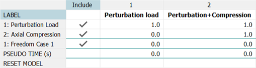
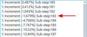
This represents the nonlinear buckling and post-buckling of a column whereby the total displacements are large in comparison with the length of the column. As the relationship between axial compression and displacement is not known, we can use the Displacement control (arc length) sub-stepping option with a Maximum displacement increment (Ratio)=0.01, say, to ensure that a result case (sub-step) will be automatically generated when the maximum displacement increment of the column exceeds 1% of its length. We only need to define a single load step (the second one in the table) to automatically produce multiple sub-steps according to the set displacement increment ratio. The load factor that produces each sub-step will be provided as part of the result case name - this is illustrated in the model window result case dropdown list shown below (VISUAL: Cases).
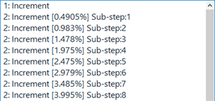
The Displacement control (arc length) option may also reverse the load in order to satisfy the set displacement increment ratio. This means that the result case dropdown list may show negative load factors before the percentage value reaches 100%.
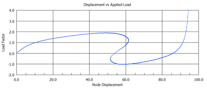
This type of result is typical of so-called snap-through type problems, such as the elastic buckling and post-buckling of a shallow arch. The following graph illustrates the force vs displacement response for such a structure. Before the load factor of 4.0 can be applied, the structure snaps though (at a load factor just below 2.0) and at some point the load factor becomes negative before eventually finding its way up to the required 4.0 value. Being able to show the equilibrium path of the structure graphically is very useful for a better understanding of the structural behaviour.
For problems that experience convergence difficulties within the set displacement increment ratios, the Minimum arc length reduction factor is available to automatically reduce the Maximum displacement increment (Ratio) and the Maximum rotation increment (deg) values. If convergence cannot be achieved in a sub-step, the ratios are halved and the sub-step starts again. This can continue to reduce up to the Minimum arc length reduction factor.
The same events that trigger sub-stepping for the Load scaling option will trigger a reduction in the Maximum displacement increment (Ratio) and the Maximum rotation increment (deg) for the Displacement control (arc length) option.
Note that if the applied load produces displacements and rotations that are below the Maximum displacement increment (Ratio) and the Maximum rotation increment (deg), the Displacement control (arc length) option does not affect the solution procedure from the point of view of automatic sub-stepping, unless convergence cannot be achieved.
Parameters
Minimum reduction factor
Specifies the minimum factor for the Load scaling and the two Displacement scaling options. This is not used by the Displacement control (arc length) option.
Maximum rotation increment (deg)
Specifies the largest allowable increment of rotation at any node, and is used as described above.
Maximum displacement increment (Ratio)
Specifies the largest allowable increment of displacement at any node as a ratio of the maximum dimension in the structure, and is used as described above.
Maximum MNL strain increment
This is applicable to nonlinear material beam elements only. The fibre strain is monitored and if a strain increment between successive increments exceeds the set limit, sub-stepping is triggered.
Minimum arc length reduction factor
Specifies the minimum arc length reduction factor for the Displacement control (arc length) option, and is used as described above.
Terminate if displacement exceeds
This option applies for all of the sub-stepping options, including None.
If set, the solver will automatically stop once the specified node displacement limit is exceeded at any node.
Terminate if rotation exceeds (deg)
This option applies for all of the sub-stepping options, including None.
If set, the solver will automatically stop once the specified node rotation limit is exceeded at any node.
Save sub-steps
If set, saves the sub-steps to the result file.
If not set, sub-stepping may still occur, but the results of the sub-steps are not saved.
Save final sub-step
This option is relevant only if Terminate if displacement exceeds or Terminate if rotation exceeds are set and the solution is terminated because of these settings, but Save sub-steps is not set. In that case, if Save final sub-step is set the final sub-step of the increment will be saved (that is, the sub-step at which the displacement and/or rotation limits were exceeded).
Common Uses
Often for a new structural analysis, the precise nature of the response is unknown and it can take several attempts to determine the best numerical procedure and load stepping strategy to use. Even for the broad categories listed below, there can still be variations in behaviour that require different levels of tuning. The most common forms of nonlinear behaviour include the following:
-
Stiffening structures
For these structures the stiffness increases with increasing load. Typically these are highly restrained structures such as built-in shells where increasing bending deformation induces membrane tension into the structure. A load control algorithm is generally sufficient for such structures.
-
Softening structures
For these structures the stiffness decreases as the load increases. The loading of solid 2D or 3D bodies in which the material yields is a typical situation. If the material stress vs strain curve has sufficient hardening, load control is usually sufficient since the overall load-displacement curve will have a positive gradient. If the material is elastic/perfectly plastic, at some limit load there can be total plastic flow and displacement control may be needed.
-
Membrane and truss structures
For these structures there is no out-of-plane stiffness until some membrane stress has been developed in the structure. Typically these include fabric tents and ship sails. A displacement scaling procedure is best suited to these applications.
-
Softening with instability
For these structures the gradient of the response curve becomes zero and some instability takes place. If the load cannot be controlled there can be dynamic motion and stability may or may not be recovered. Such structures are the most difficult to analyse and the best solution algorithm is a mixture of the load scaling and arc length methods.
See Also