Brick Elements: Local Axes
Local x, y, z axes
The default local axis system of brick elements coincides with the global axis system. The axes may also be aligned to any UCS via the Brick Attributes: Local Axes attribute.
Local axes on brick elements are important for the following purposes:
- assignment of pre-stress and pre-strain attributes in a particular direction;
- definition of material axes for non-isotropic material properties; and
- viewing of results in the local axis system.
Local face x, y axes (direction on brick faces)
The direction of Brick Attributes: Face Shear Stress is defined by local x, y axes on the face of a brick. These local axes match the local axes of a plate element connected directly on top of the brick face to the same nodes, with the plate element having the same shape as the brick face (i.e., triangular or quadrilateral) and connected with its normal pointing outward.
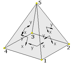
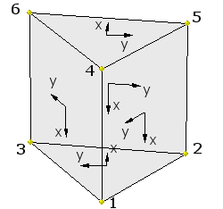
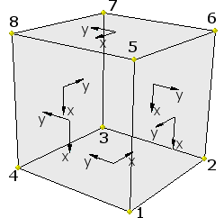
The following images illustrate the local face axes for each type of brick element.
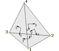
The face definitions for each brick type (i.e., the equivalent plate corner nodes) are tabulated below.
|
Brick Type |
Face |
Equivalent Plate Nodes |
|
Tetrahedron |
1 |
1-2-3 |
|
|
2 |
4-1-3 |
|
|
3 |
4-2-1 |
|
|
4 |
4-3-2 |
|
Pyramid |
1 |
1-2-3-4 |
|
|
2 |
5-1-4 |
|
|
3 |
5-2-1 |
|
|
4 |
5-3-2 |
|
|
5 |
5-4-3 |
|
Wedge |
1 |
1-2-3 |
|
|
2 |
5-2-1-4 |
|
|
3 |
4-6-5 |
|
|
4 |
4-1-3-6 |
|
|
5 |
6-3-2-5 |
|
Hexahedron |
1 |
1-2-3-4 |
|
|
2 |
7-3-2-6 |
|
|
3 |
6-5-8-7 |
|
|
4 |
5-1-4-8 |
|
|
5 |
8-4-3-7 |
|
|
6 |
6-2-1-5 |
Local u, v axes (position on brick faces)
Similar to Plate Elements: Local Axes, the position on brick faces can be described by using the local u-v coordinates. The u-v coordinate range is always defined to be between -1 and +1 for quadrilateral faces and between 0 and +1 (with some restrictions) for triangular faces.
Triangular Brick Faces
The figure below shows the u-v coordinates for triangular brick faces.
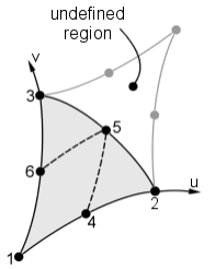
| Node | Coordinates | |
| u | v | |
| 1 | 0 | 0 |
| 2 | 1 | 0 |
| 3 | 0 | 1 |
| 4 | 0.5 | 0 |
| 5 | 0.5 | 0.5 |
| 6 | 0 | 0.5 |
Quadrilateral Brick Faces
The figure below shows the u-v coordinates for quadrilateral brick faces.
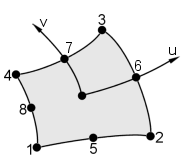
| Node | Coordinates | |
| u | v | |
| 1 | -1 | -1 |
| 2 | 1 | -1 |
| 3 | 1 | 1 |
| 4 | -1 | 1 |
| 5 | 0 | -1 |
| 6 | 1 | 0 |
| 7 | 0 | 0 |
| 8 | -1 | 0 |
Local u, v, w axes (internal position of bricks)
The position on the inside of a brick element can be described by using the local u-v-w coordinates.
The u-v coordinate range is defined to be between -1 and +1 if the base face is quadrilateral (i.e., pyramid, hexahedron), and between 0 and +1 (with some restrictions) if the base face is triangular (i.e., wedge, tetrahedron). Similarly, the w coordinate is between -1 and +1 if the height/depth face is quadrilateral (i.e., wedge, hexahedron), and between 0 and +1 if the height/depth face is triangular (i.e., pyramid, tetrahedron).
Note that the u and v values defined in the u-v-w system can be different to the u and v values on brick faces.
One use of these local coordinates if for the definition of the attachment points of nodes insides brick elements, such as might be required to attach a beam element to the inside of a brick element (see Insert: Attachment Link).
Tetrahedra
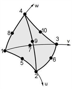
| Node | Coordinates | ||
| u | v | w | |
| 1 | 0 | 0 | 0 |
| 2 | 1 | 0 | 0 |
| 3 | 0 | 1 | 0 |
| 4 | 0 | 0 | 1 |
| 5 | 0.5 | 0 | 0 |
| 6 | 0.5 | 0.5 | 0 |
| 7 | 0 | 0.5 | 0 |
| 8 | 0 | 0 | 0.5 |
| 9 | 0.5 | 0 | 0.5 |
| 10 | 0 | 0.5 | 0.5 |
Pyramids
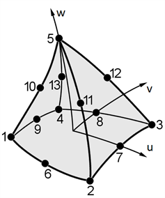
| Node | Coordinates | ||
| u | v | w | |
| 1 | -1 | -1 | 0 |
| 2 | 1 | -1 | 0 |
| 3 | 1 | 1 | 0 |
| 4 | -1 | 1 | 0 |
| 5 | 0 | 0 | 1 |
| 6 | 0 | -1 | 0 |
| 7 | 1 | 0 | 0 |
| 8 | 0 | 1 | 0 |
| 9 | -1 | 0 | 0 |
| 10 | -0.5 | -0.5 | 0.5 |
| 11 | 0.5 | -0.5 | 0.5 |
| 12 | 0.5 | 0.5 | 0.5 |
| 13 | -0.5 | 0.5 | 0.5 |
Wedges
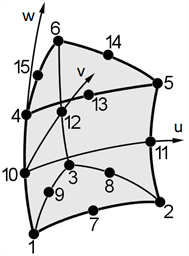
| Node | Coordinates | ||
| u | v | w | |
| 1 | 0 | 0 | -1 |
| 2 | 1 | 0 | -1 |
| 3 | 0 | 1 | -1 |
| 4 | 0 | 0 | 1 |
| 5 | 1 | 0 | 1 |
| 6 | 0 | 1 | 1 |
| 7 | 0.5 | 0 | -1 |
| 8 | 0.5 | 0.5 | -1 |
| 9 | 0 | 0.5 | -1 |
| 10 | 0 | 0 | 0 |
| 11 | 1 | 0 | 0 |
| 12 | 0 | 1 | 0 |
| 13 | 0.5 | 0 | 1 |
| 14 | 0.5 | 0.5 | 1 |
| 15 | 0 | 0.5 | 1 |
Hexahedra
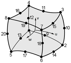
| Node | Coordinates | ||
| u | v | w | |
| 1 | -1 | -1 | -1 |
| 2 | 1 | -1 | -1 |
| 3 | 1 | 1 | -1 |
| 4 | -1 | 1 | -1 |
| 5 | -1 | -1 | 1 |
| 6 | 1 | -1 | 1 |
| 7 | 1 | 1 | 1 |
| 8 | -1 | 1 | 1 |
| 9 | 0 | -1 | -1 |
| 10 | 1 | 0 | -1 |
| 11 | 0 | 1 | -1 |
| 12 | -1 | 0 | -1 |
| 13 | -1 | -1 | 0 |
| 14 | 1 | -1 | 0 |
| 15 | 1 | 1 | 0 |
| 16 | -1 | 1 | 0 |
| 17 | 0 | -1 | 1 |
| 18 | 1 | 0 | 1 |
| 19 | 0 | 1 | 1 |
| 20 | -1 | 0 | 1 |
See Also