Results Interpretation: Stress Conventions
Description
Plate and brick stress results are available in the element's local axes and can be transformed to the global axes and user coordinate system (UCS) or combined to produce other quantities such as principal stresses. The directions and sign conventions of these result quantities are summarised below.
Local Stress Components
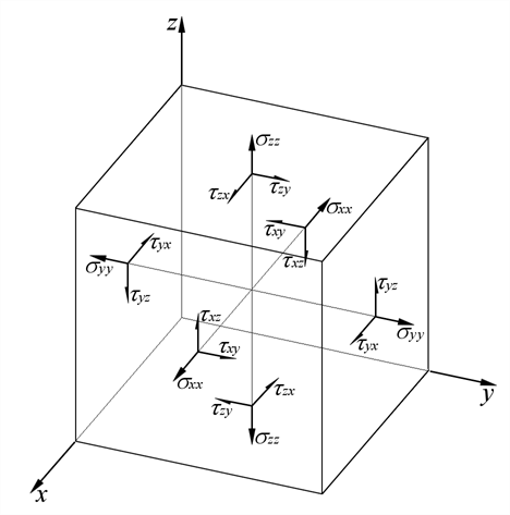
Stress of an element at a point can be described as a local stress tensor with the following normal and shear components. The conventions below show all positive local stress components.
where
 ,
,  ,
,  are normal stresses in the local x, y and z axes respectively.
 ,
,  ,
,  are shear stresses and
  ,
,  ,
,  .
.
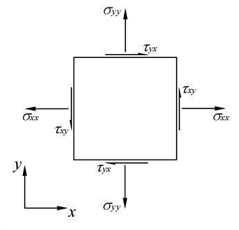
The above conventions apply to both plate and brick elements. For plate elements, thickness is in the z axis and the in-plane axes are x and y. The above illustration, if simplified to just the in-plane axes, is shown below:
Axis Transformation
The local stress tensor can be transformed to other axis system. The subscripts of the stress quantities change to reflect such transformation. For example,  refers to normal stress in the global X axis while
  refers to radial stress.
The local stress tensor can also be transformed to the principal axes in which case the subscripts change to 11, 22 and 33 (e.g.,  ). Stresses can also be combined according to specific rules and criteria to form effective stresses such as von Mises stress,
  .
.
Mean and Deviatoric Stresses
The local stress tensor can be decomposed into two parts - mean and deviatoric parts.
The mean part, also known as the hydrostatic or volumetric part, is calculated as the average of the three normal stress components:

The deviatoric part (i.e., the deviation in stresses), is calculated as the difference between the mean stress and the three normal stress components:

Deviatoric stresses in the global and principal axes are calculated similarly. For example:

Sign Convention
Direct stresses (e.g.,  ) and principal stresses (e.g.,
  ) are given as positive when tensile and as negative when compressive. For various other stress components, including shear, deviatoric, von Mises, Tresca, Mohr-Coulomb and Drucker-Prager, the sign of the stress does not indicate tension or compression.
See Also