Element Result Settings: Entity Tabs
Description
Results display options for beams, plates, bricks and links.
Dialog
Settings...
Options for configuring the result style and legend.
See Result Settings: Settings.
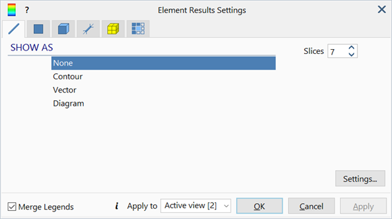
Slices
Number of slices along the beam's length used to produce diagrams or contour plots.
Applicable to beam results only. See Results Interpretation: Beam Slices.
Facet
Maximum angle between the normals of any two adjacent plates for results to be averaged, applicable to plate/shell element results only.
If the facet option is set, results are averaged when the angle between normals on adjacent plates is less than or equal to the Facet angle.
If the facet option is not set, the angle check is skipped.
This criterion, if set, is applied in addition to others such as Average Same Property number; only when all the criteria are satisfied will results be averaged.
Ply num
Specifies the ply number for which results are to be displayed when Specified Ply is set in the ply selection section.
Applicable to laminate plate results only.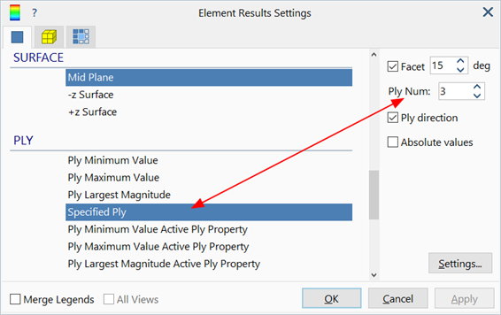
Ply direction
If set, draws the direction of the selected ply according to its angle definition in LAYOUTS: Laminates.
Applicable to laminate plate results only.

Ref. Node
Number of a reference node used to compute relative displacements.
If provided, displacement results are given relative to the displacement of the reference node. This is done by subtracting the displacements of the reference node from all other nodes.
Normalise to Yield
If set, beam stress values are contoured as ratios relative to their respective tensile and compressive yield stress values. Yield stress values are the first stress values beyond the (0.0, 0.0) point in the stress-strain table (i.e., the point at which the tangent in the table changes compared with the initial tangent).
The option is applicable to elastic and elastic-plastic beam elements with stress-strain curve assigned.
Absolute values
If set, displays result magnitudes only, ignoring the sign.
Subtract supports
If set, the reactions due to element support attributes (Beam Attributes: Support, Plate Attributes: Support and Brick Attributes: Face Support) are subtracted from the total reaction at nodes before plotting reaction contours or vectors.
This setting is typically used in conjunction with node reaction contours to identify areas with large unbalanced forces in nonlinear analyses; by subtracting the reactions due to the support, the remaining reactions will be just the unbalanced forces. Large unbalanced forces are usually observed in an unconverged nonlinear solution.
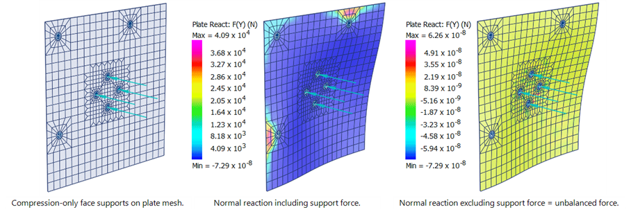
This setting does not apply to elements with no support attributes.
Inactive support as
This controls how surfaces without support attributes or with inactive support attributes should be rendered when plotting contours of support results such as support pressure. Those surfaces can be presented in one of the following ways:
- Wireframe
Surfaces with zero support stress are not contoured. Instead only their element outlines are drawn according to the entity display settings (Entity Display Settings: Plate Display, Entity Display Settings: Brick Display).
- As zero
This option extends the range of the contour legend to include zero, if not already included. Surfaces with zero support stress are then contoured as having a stress of zero.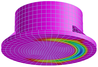
- Limit min colour
Surfaces with zero support stress are contoured using the limit min colour specified in Contour Configuration: Style Tab.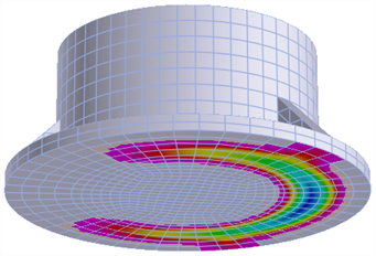
- Limit max colour
Surfaces with zero support stress are contoured using the limit max colour specified in Contour Configuration: Style Tab.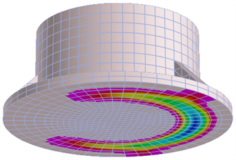
Inactive RC Layer as
This controls the display of plate RC results when showing plate elements in the Solid plate style. RC results for solid plates are shown only on the surface of the plate corresponding to the RC layer requested (layers 1 and 2 are on the -z surface, while layers 3 and 4 are on the +z surface). This option control how the other surface and the edges of the thick plate are contoured. The options are the same as for Inactive support as, that is, Wireframe, As zero, Limit min colour or Limit max colour.
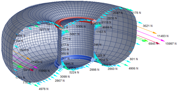
Vector labels
If set, displays a text label next to vectors with the numeric value of the result at that point.
Vector units
If set, appends the units of the result quantity to the vector label.
Applicable only if Vector labels is set.
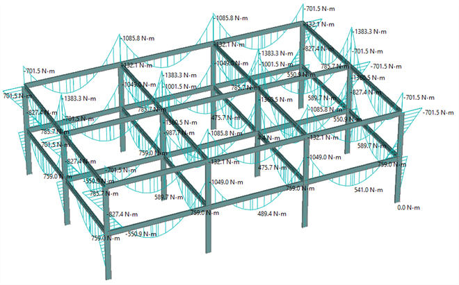
Diagram labels
If set, result diagrams are displayed with value labels.
Applicable to beam results only.
Diagram units
If set, result diagrams are displayed with units.
Applicable only if Diagram labels is set.
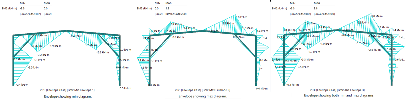
Both limit envelopes
If set, result diagrams of any limit envelope case (see CASES: Envelope Cases) are displayed with both the minimum and the maximum values at the same time.
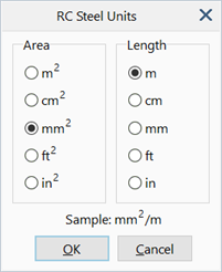
RC steel units
Sets the units of area per length for steel reinforcement area results.
Common Controls
Result Options
The following options are available under each entity tab.
SHOW AS
-
None
Results are not shown for the selected entity.
-
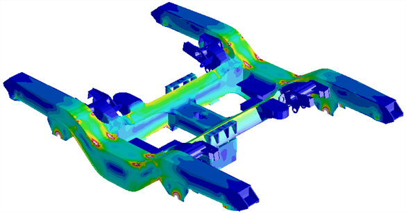
Contour
Displays result quantities as a contour rendered on the element surface.
-
Vector
Displays result quantities as a vector field.
Applicable only to results that have a vector representation.
These include principal stress vectors on plate and brick elements,
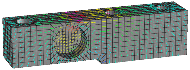
and nodal quantities such as displacement and reaction vectors.
-
Diagram
Displays force and moment result quantities as diagrams along the length of beam elements.
QUANTITY
Result quantity to display.
Only result quantities applicable to the selected entity type are listed. See Results Interpretation: Result Quantities.
SOIL STRESS
Stress results for soil materials can be presented as either effective stress or total stress. See Results Interpretation: Result Quantities.
SYSTEM
Axis system in which the selected result quantity is expressed.
Depending on the entity and quantity type, available axis systems may be Principal, Local, Global, UCS, Restraint UCS and Combined. Combined indicates result quantities that comprise multiple components to produce a result; these include principal stress and von Mises stress. Restraint UCS refers to the UCS of the restraint attribute applied to the node, in the 1-2-3 system (i.e., first, second and third axis of the UCS).
COMPONENTS
Component of the selected result quantity to display. Most result quantities comprise multiple components.
INCLUDE
Specifies whether to consider all nodes, fixed nodes or free nodes for result display.
Applicable only to node reaction results.
EQUATION
Mathematical expression of the user-defined result quantity.
This is available for the User-defined Result quantity only.
-
Edit equations
Opens Results: Element Results Equations for defining and editing user-defined equations.
DIRECTIONS
Component to display for selected vector result quantity.
SURFACE
Plate or ply surface on which results are displayed.
PLY
Ply options for laminates to display specific results such as the minimum or maximum value of all plies, only a specific ply, the ply with the largest magnitude, etc.
Active plies are selected under Element Result Settings: Property/Ply/Link Type Selections Tab, which enables the filtering of plies based on the ply property type, so that ply types can be included or excluded from the results as required.
EXTRAPOLATION
Method used to extrapolate and interpolate results from Gauss points over the rest of the element domain.
Applicable to plate and brick elements only.
See Results Interpretation: Gauss Point Extrapolation and Averaging.
AVERAGING
Method used to average results displayed at nodes that are shared by multiple elements.
Applicable to plate and brick elements only.
See Results Interpretation: Gauss Point Extrapolation and Averaging.
SCALE ON
Method used to set the display size of result vectors drawn on element surfaces.
Applicable to plate and brick elements only for the presentation of principal stress vectors.
See Also
- Result Settings: Settings
- Results: Element Results Equations
- Results Interpretation: Result Quantities
- Element Result Settings: Group Selections Tab
- Element Result Settings: Property/Ply/Link Type Selections Tab
- Results Interpretation: Gauss Point Extrapolation and Averaging
- Results Interpretation: Expanded Envelope Results