Results Interpretation: Result Quantities
Description
A glossary of result quantities is tabulated below.
| Quantity | Description |
| Node Displacement |
Translations and rotations of a node. For example, D(X), D(Y), D(Z), R(X), R(Y), R(Z) are translations in and rotations about the first, second and third axis respectively of either the global or the user-defined coordinate system (UCS). Magnitudes of resultant vectors are also available, for example:
In Results: Peek and The LISTINGS Tab, original node coordinates before displacement in global XYZ or UCS (e.g., X, Y, Z), and the coordinates after displacement (e.g., X', Y', Z'), are also given for reference. For example:
If a reference Ref. Node is specified, the displacement is calculated relative to the displacement of the reference node. These are calculated as 'displacements at point' minus 'displacements at reference node'. For example, if relative
|
| Node Velocity | Linear velocities and angular velocities of a node. For example, V(X) and VR(X) are linear velocity in, and angular velocity about, the X axis respectively. Magnitudes of resultant vectors are available and are derived similarly to those of Node Displacement. |
| Node Acceleration | Linear accelerations and angular accelerations of a node. For example, A(X) and AR(X) are linear acceleration in, and angular acceleration about, the X axis respectively. Magnitudes of resultant vectors are available and are derived similarly to those of Node Displacement. |
| Node Reaction |
External force and moment reactions at a restrained or supported node. For example, F(X) and M(X) are force reaction in, and moment reaction about, the X axis respectively. Magnitude of resultant vectors are available and are derived similarly to those of Node Displacement. Node reactions can be reported in the Global system, UCS or Restraint UCS. Node reactions of brick elements can also be reported in the brick's local axes. Restraint UCS refers to the UCS of the restraint attribute applied to the node, in the current results case and in the 1-2-3 system (i.e., the first, second and third axis of the UCS). |
| Element Node Force |
Similarly to Node Reaction, element node forces are free body forces and moments at a node that balance the element's internal forces and moments, irrespective of whether the node is restrained or not. |
|
Link Node Force |
Similarly to Node Reaction, link node forces are the sum of Element Node Force results produced by the elements connected to the link node. For Reaction MPLs, the forces are the sum of the results contributed by the connected elements contained in the Entity Set referenced by the MPL. |
| Node Phase |
Phase angles of the node translations and rotations in degrees, available for Harmonic Response results. For example, P(X) and PR(X) are phase angles in and about the X axis respectively. Magnitude of resultant vectors are available and are derived similarly to those of Node Displacement. See Solvers Overview: Harmonic Response. |
| Node Inertia Force | Similar to Node Reaction, node inertia forces are pseudo forces that resist the change in accelerations of a node, available in the Harmonic Response and Spectral Response results. If the node has no mass or no accelerations, its inertia force is zero. |
| Node Temperature | Temperature at a node in either Celsius, Kelvin, Fahrenheit or Rankine. |
| Node Flux | The rate of heat exchange (i.e., energy flow rate), at a node. Positive node flux is inflow and negative node flux is outflow. |
| Element Flux |
The rate of heat flow per unit area. Positive value means that the heat energy flows in the same direction as the selected axis while negative value indicates that the heat energy flows in the opposite direction. For beam elements, the axis is the beam's principal 3 axis (see Beam Elements: Local and Principal Axes). For plate and brick elements, the axis can be a local x, y, z axis, a global axis or a user-defined coordinate system (UCS) axis (see Plate Elements: Local Axes and Brick Elements: Local Axes). Magnitude calculation is similar to that of Node Displacement. |
| Element Temperature Gradient |
Difference in temperature per unit length in a selected axis. Positive value means temperature is increasing along the axis while negative value indicates that the temperature is decreasing along the axis. For beam elements, the axis is the beam's principal 3 axis (see Beam Elements: Local and Principal Axes). For plate and brick elements, the axis can be a local x, y, z axis, a global axis or a user-defined coordinate system (UCS) axis (se Plate Elements: Local Axes and Brick Elements: Local Axes). Magnitude calculation is similar to that of Node Displacement. |
| End Release | For geometry linear analysis, this is the release displacement relative to the position of the node from which the beam end is detached. For geometry nonlinear analysis, this is the release displacement relative to the current position of the end of the beam. See Results Interpretation: Beam End Release Conventions. |
| Reaction MPL |
The summation of forces and moments of linked nodes about the origin of the Reaction multi-point link. See Entities: Links. |
| Beam End Force |
Internal forces of a beam element with reference to its local, principal, global or a user-defined coordinate system at the beam ends. Internal forces includes:
See Results Interpretation: Beam Force and Moment Conventions. |
| Beam Axial Strain | Beam displacements in the axial direction as a ratio of the beam's initial or current length. See Results Interpretation: Total, Deformation, Nominal and Engineering Strain. |
| Beam Curvature | The reciprocal of the radius of a circular arc that describes the beam's displacement curve at a point on the beam. The beam curvature is given in the beam's principal planes. See Beam Elements: Local and Principal Axes. |
| Beam Twist | Total twist angle in radian per unit length about the principal 3 axis of the beam. For example, a 1.5 m beam with a 5 degree (0.087266 radian) twist produces a uniform twist of 0.087266/1.5 = 0.0581776 /m. |
| Beam Axial Stress |
Axial force experienced by a beam element per its cross section area at that point:
|
| Beam Bending Stress |
Fibre stress on the cross section of a beam element due to pure bending moments in the principal planes. Note that positive bending moment produces compressive (i.e., negative), stress in fibres above the centroid.
|
| Beam Fibre Stress |
Total stress of a fibre on the cross section of a beam due to bending moments and axial force. Shear actions are excluded. Beam section shape must be defined for stresses to be calculated.
|
| Beam Fibre Strain |
Similar to Beam Fibre Stress, fibre strain is the axial displacements of a fibre as a ratio of its initial or current length due to bending moments and axial force. See Results Interpretation: Total, Deformation, Nominal and Engineering Strain. Catenary cable element is an exception of which the fibre strain is defined as:
where
See also Results Interpretation: Total, Deformation, Nominal and Engineering Strain. |
| Beam Shear Stress |
Stress that is parallel to the cross section and at a point on the cross section of a beam element.
|
| Beam Yield Area Ratio |
The ratio of cross section area that has yielded. For example, a value of 0.75 means that 75% of the cross section area at that particular station along the beam has yielded. For bending elements (for example, Beam Properties: Beam type elements), the yield ratio is between 0.0 and 1.0. For non-bending elements (for example, Beam Properties: Truss type elements), the yield ratio is either 0.0 or 1.0. For beams with Moment-Curvature and Axial Stress vs Strain tables, where each of the bending and the axial directions can yield independently, the yield ratio can be one of 0/3, 1/3, 2/3, 3/3, where the numerator refers to the number of axes that have yielded (e.g., 2/3 could mean that it has yielded about one of the axes and in the axial direction). The same convention is adopted for Beam Properties: Connection type elements which can have up to six different tables (hence valid yield ratios are 0/6, 1/6 … 6/6). |
| Pipe Hoop Stress | Circumferential stress in the pipe wall, available for pipe elements only. |
| Mean Stress / Strain |
The average of the three normal stress or strain components. Also known as the hydrostatic or volumetric part of a stress tensor. See Results Interpretation: Stress Conventions. |
| Deviatoric Stress |
The difference between the mean stress and the three normal stress components. See Results Interpretation: Stress Conventions. |
| Principal Stress / Strain |
Principal stresses are normal stresses in an axis system in which shear stresses are all zero. The most positive principal stress is denoted For beam elements, the principal stress combines the fibre stress and shear stresses due to torque and transverse shear forces. Similarly for principal strains. |
| Principal 11 Angle | The angle measured from the plate element's local x axis to the principal 11 axis. |
| von Mises Stress / Strain |
An effective stress according to the following equation:
Similarly for von Mises strain. |
| Tresca Stress / Strain |
An effective stress according to the following equation:
Similarly for Tresca strain. |
| Max Magnitude Stress / Strain |
The principal stress with the largest magnitude.
Similarly for Max Magnitude strain. |
| Mohr-Coulomb Stress |
An indicator according to the Mohr-Coulomb yield criterion. The value is a stress difference; that is, a measure of how far a stress point is from the yield surface. Positive value indicates that the material stress state is outside the yield surface (i.e., material failure).
where
|
| Drucker-Prager Stress |
An indicator according to the Drucker-Prager yield criterion that combines the Mohr-Coulomb and von Mises criteria. The value is a stress difference; that is, a measure of how far a stress point is from the yield surface. Positive value indicates that the material stress state is outside the yield surface (i.e., material failure).
where
|
| Yield Index | An indicator of the material yield status at Gauss points. The index can either be 0.0 (not yielded) or 1.0 (yielded). When contouring and extrapolating, there may be intermediate values between 0.0 and 1.0 if the element has some Gauss points that have yielded and some that have not yielded. |
| Edge / Face Support Stress | The bearing pressure at the plate edges, plate faces or brick faces with Plate Attributes: Edge Support, Plate Attributes: Face Support or Beam Attributes: Support, respectively. |
| Cavity Stress | The pressure inside the LAYOUTS: Cavities. |
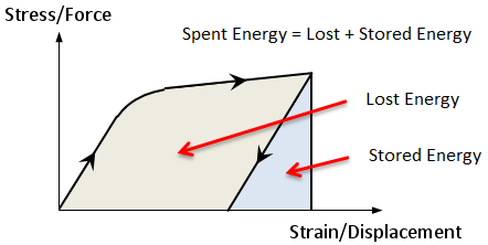
| Energy Density |
Strain energy per length of beam element, per area of plate element, or per volume of brick element, due to element strain and deformation. Note that this result quantity does not include the kinetic energy of the element in transient dynamic analysis.
Element Strain must be included in the results file for energy results to be calculated. |
| Energy Integral |
This is the integral of Energy Density results. Energy integral is given as a single value per element, in absolute energy units such as Joules. Element Strain must be included in the results file for energy results to be calculated. |
| Energy Sum |
This is the total energy obtained by summing the energy integrals of all elements that are currently visible and contoured. The value is given at the base of the energy density contour legend. |
| User-defined Result | User-defined result equation based on various components of forces, stress and strain. See Results: Element Results Equations. |
| Cable XYZ |
The positions along the cable element in the global XYZ system. Positions at up to 20 slices are available. This results quantity is only available in Results: Peek and The LISTINGS Tab. |
| Plate Element Force |
Plate element's normal forces, in-plane shear force and transverse shear forces expressed in either the local x, y, z axes, the global axes or the axes of a user-defined coordinate system (UCS) (see Plate Elements: Local Axes). Similarly to stresses, plate element forces can be transformed to the principal axes and combined. See Results Interpretation: Plate Shear Force and Moment Conventions. |
| Plate Bending Moment |
Plate element's bending moments expressed in either the local x, y, z axes, the global axes or the axes of a user-defined coordinate system (UCS) (see Plate Elements: Local Axes). Similarly to stresses, plate element bending moments can be transformed to the principal axes and combined. See Results Interpretation: Plate Shear Force and Moment Conventions. |
|
Plate Force/Moment |
Shows both the plate element force and bending moment results on the same page. This also applies to Results Interpretation: Expanded Envelope Results to determine equilibrated force and moment components for a given envelope value. |
| Element Strain | The displacements of an element as a ratio of its initial or current size. Similarly to stresses, element strains can be transformed to the principal axes and combined. See Results Interpretation: Stress Conventions and Results Interpretation: Total, Deformation, Nominal and Engineering Strain. |
| Plastic Strain | Permanent strain that is caused by mechanical loads when an elastic-plastic material yields. Plastic strains in material are not recoverable when the mechanical loads are removed. |
| Plate Curvature | The reciprocal of the radius of a circular arc that describes the plate's displacement curve. Similarly to stresses, plate curvature can be transformed to the principal axes and combined. See Results Interpretation: Stress Conventions. |
| Creep Strain | Strain caused by creep according to the specified creep data. See LAYOUTS: Creep. |
| Effective Rate | The effective creep strain rate, which is the time derivative of the specified metal creep data. |
| Shrinkage Strain | Strain caused by shrinkage according to the specified concrete creep and shrinkage data. See Creep: Concrete Creep and Shrinkage - Shrinkage. |
| Composite Ply Stress / Strain |
Normal and shear stresses of the ply material that forms the laminate stack.
Interlamina shear is reported in between the plies and is zero at the outermost surfaces of the laminate. For example, the interlamina shear reported for Ply 1 is the shear stress at the top of Ply 1 (i.e., at the interface between Ply 1 and Ply 2). As with other stress quantities, ply stresses can be transformed to the principal axes and combined. See Results Interpretation: Stress Conventions. Similarly for Composite Ply Strain. |
| Composite Ply Reserve Factor |
Reserve factor is generally a ratio between the allowable load at failure of the ply material and its current applied load, i.e.:
The ply is considered safe if the reserve factor is greater than 1. The allowable load at failure is defined under LAYOUTS: Plies.
|
| Plate Reinforced Concrete Results |
Quantities include:
|
| Effective Stress (Soil) |
Soil stress excluding pore pressure.
|
| Total Stress (Soil) |
Soil stress including pore pressure.
|
| Total Pore Pressure |
The total pore pressure, which includes the initial and the excess pore pressures. |
| Excess Pore Pressure |
Pressure built up inside the void of undrained soil material as the material compacts and deforms. Additional pressure can build up when liquid within the void is confined from flowing freely when the external load changes. Pore pressure is available for undrained soil only. |
| OCR |
Over Consolidation Ratio is the ratio of the past effective pressure (pre-consolidation pressure) to the current overburden pressure. A normally consolidated soil has OCR=1, an over-consolidated soil has OCR>1. OCR is available for Modified Cam-Clay Soil only. |
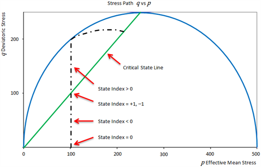
| State Index |
State index ranges from -1 to +1. A negative value of state index indicates that the soil p-q state is below the critical state line; a positive value of state index indicates that the soil p-q state is above the critical state line. The state index approaches the critical state line as it increases. State index is available for Modified Cam-Clay Soil only.
|
| Void Ratio |
The ratio between the current volumes of void and solid components of soil material.
Although the void ratio is a pre-defined property of soil material, for Modified Cam-Clay Soil, the void ratio might change as the material compacts and deforms. |


 quantities are requested, these are calculated as
  minus
minus  , not the
  of the difference in
  and
and  of the respective points. That is:


 is the bending moment in plane 1,
  is the second moment of area about principal 2 axis and
  is the projected distance in the principal 1 axis from section centroid to a point on the cross section.
 is the bending moment in plane 2,
  is the second moment of area about principal 1 axis and
  is the projected distance in the principal 2 axis from section centroid to a point on the cross section.

 = mechanical or total strain in the cable,
 = position along the cable,
 = deformational strain at
  ,
, = axial force at
  ,
, = cable cross section area,
 = Young’s modulus,
 = cable free length (for cables without the free length attribute,
  is equal to the initial distance between the nodes),
 = initial cable length (that is, the stress-free length of the cable)
  ,
, = uniform thermal (engineering) strain along cable length (due to node temperature attributes), and
 = (engineering) pre-strain (due to pre-strain attributes) uniform along the cable length.
 , followed by
  and
and  (i.e.,
  ). The corresponding axes in which these principal stresses act are called principal axes.


 = material cohesion, and
 = material internal friction angle.
 = material cohesion
 = material internal friction angle


 ,
,  ,
,  are the allowable stresses in the fibre 1, 2 and in-plane shear respectively.
  is the tensile limit if the corresponding ply stress is positive and compressive limit if the corresponding ply stress is negative.
 ,
,  ,
,  are the allowable strains in the fibre 1, 2 and in-plane shear respectively.
  is the tensile limit if the corresponding ply strain is positive and compressive limit if the corresponding ply strain is negative.


 ,
,  ,
,  ,
,  and
and  are the same as those of the Hoffman criterion above.
 is the interaction coefficient obtained from the determination of ply strength under equal biaxial tensile loading and is taken as zero in

 is the allowable interlamina shear stress.


See Also
- Element Result Settings: Entity Tabs
- New Graph: Quantity Tab
- Results Peek: Entity Tabs
- Results: Element Results Equations
- Results Interpretation: Plate RC
- Results Interpretation: Stress Conventions
- Results Interpretation: Plate Shear Force and Moment Conventions
- Results Interpretation: Total, Deformation, Nominal and Engineering Strain
- Results Interpretation: Beam End Release Conventions