Results Interpretation: Beam End Release Conventions
Description
Strand7 beam elements can be released (i.e., detached) from the nodes to which they are connected by the application of beam end release attributes (Beam Attributes: Rotation End Release, Beam Attributes: Translation End Release). All six degrees of freedom at the end of the beam can be released for geometrically linear analysis. For geometric nonlinear analysis, four of the six degrees of freedom can be released (the missing ones are the lateral translational releases). End release attributes can be used to fully detach a beam end from its node, or to connect it using a spring of predefined stiffness (i.e., to partially release it).
Because a released beam end is no longer fully connected to its node, the displacements at the beam end, for the released degrees of freedom, may be different to the displacements at the node. To enable the beam displacements to be correctly reported in post-processing, these end release displacements (translations and/or rotations) become available.
End release translations and rotations are reported in the beam element axis system in which they are defined, with reference to the position of the node at which the beam is attached. The convention used to report these values in a geometrically linear analysis is different to the convention used in a geometrically nonlinear analysis.
For geometrically linear results, end release translations and rotations are reported in and about the directions of the beam principal axes in the beam's initial undeformed orientation, with respect to the original position of the node.
For geometrically nonlinear results, end release translations and rotations are reported in and about the directions of the beam principal axes in the beam's current deformed orientation, with respect to the current (displaced) position of the node.
These conventions are further illustrated below.
See Beam Elements: Local and Principal Axes.
Translations
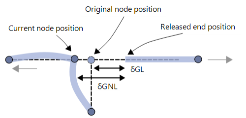
The illustration below represents three beam elements connected to the same node as a T-junction. One element is fully released in the axial direction. This element displaces to the right while the other two elements displace to the left.

-
Linear geometry
The end release translations,
, are relative to the end node position in the undeformed configuration.
-
Nonlinear geometry
The end release translations,
, are relative to the end node position in the current deformed configuration.
Rotations
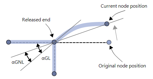
The illustration below represents three beam elements connected to the same node as a T-junction. One element is fully released in the rotational bending direction. This element rotates relative to the node at which it is released.

-
Linear geometry
The end release rotations,
, are relative to a line passing through the nodes in the undeformed configuration. That is, the reference is the principal 3 axis of the beam in the initial position.
-
Nonlinear geometry
The end release rotations,
, are relative to the line passing through the nodes in the current deformed configuration. That is, the reference is the principal 3 axis of the beam in the current position.
Beam Offset and Beam End Release
If the beam is offset from the nodes, the end release is applied directly to the offset ends of the beam, not to the position of the nodes. In other words, a beam end release attribute releases the beam, not the node.
See Also