Plate Elements: Load Patches
Description
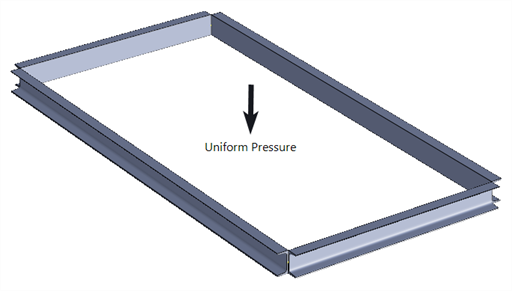
Load patches provide a convenient mechanism for the application of distributed area loads and mass to beam elements. Typical applications include live loads on floor slabs transferred to beams and wind loads on buildings transferred to columns. To illustrate the basic concept, consider the following four beams forming a rectangle, onto which a uniform pressure load is to be applied:
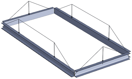
An approximation to the equivalent line loads on each beam can be obtained by considering the tributary area of the rectangle associated with each beam. For this configuration it leads to the following distribution:
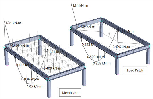
The following figure shows the resulting bending moment on one of the longer beams, for a uniformly distributed area load. In the case on the left, the load is applied via an 8×4 mesh of membrane elements, solved considering geometric nonlinearity to ensure that only a vertical load is applied, with no moments. In the case on the right, the load is applied via a single load patch, with a single element spanning between columns. Reasonable agreement is seen between the two representations indicating that accurate distributed loads can be easily applied to beam models with this approach.
Load patch is a sub-type of plate element, specified under Plate Properties: Load Patch.
Area loads and masses applied to the load patch plates are redistributed to the beam elements along the edges. Plate Attributes: Load Patch Type can be used to specify how the patch load is to be redistributed to the edges. A number of different variations are available.
To automatically insert load patch plates over a structure (e.g., on a roof), use Insert Multi-element: Load Patch Plates on Beam Polygons.
Load Transfer Mechanism
The total load applied to surrounding beams will be equal to the total load applied to the load patch, provided there are beams along all the loaded edges of the load patch to take the patch load. If there is no beam along any part of a loaded edge, that load portion is lost (a warning message is given when solving a model with missing patch loads).
The presence of a beam along an edge of the patch plate is dictated by the tolerance set in Plate Properties: Load Patch. This enables load transfer even if the beams are not perfectly overlaid on the plate edge.
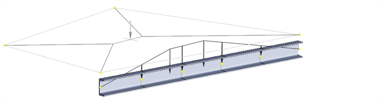
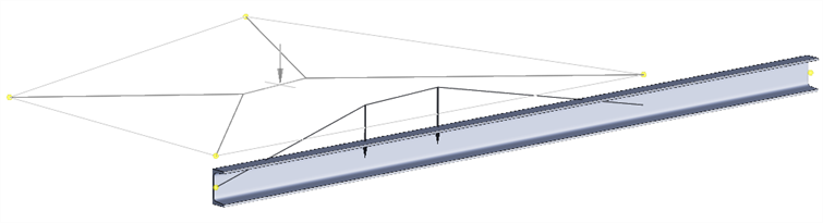
An edge may be spanned by a single beam element, as shown below,
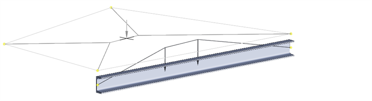
or it may be spanned by more than one beam element, as shown below,
or it may be spanned by only a part of a beam, as shown below:
In all these cases, the correct amount of load will be distributed to the beam element(s) in question.
Note that loads assigned to the load patch plate remain as patch loads until the solver is launched. Patch loads are then converted to beam loads for the solver just before the solver launches. The solver then operates with the beam loads, and not with the patch loads.
Prior to running the solver, the Convert Tools: Patch Loads to Beam Loads can be used to check and inspect the load transfer. Loads can be permanently transferred to the beams, but in that case they should be deleted from the patch plates otherwise they will be applied twice when the solver is launched.
Note also that load patches have straight edges; i.e., the mid-side nodes of Quad8 or Quad9 elements are not considered for load patch distribution.
Applicable Plate Attributes
The following plate attributes applied to load patches are transferred to beam elements:
- Plate Normal Pressure
- Plate Global Pressure (projected and not projected)
- Plate Face Shear
- Plate Non-Structural Mass
The plate face loads are converted to Beam Attributes: Global Distributed Force. The plate non-structural mass is converted to Beam Attributes: Non-structural Mass.
See Also