Strand7 Interface: Strand7 Layout
Description
The Strand7 Interface offers the possibility of opening multiple models simultaneously, each in its own window with its own set of tabs, menus and icons.
By default, the Strand7 model window opens up in The VISUAL Tab in Expanded mode. If you prefer a dropdown menu style, you can switch to Compact mode via the Show/Hide Menu icon near the top right corner of the model window (see Strand7 Layout: Compact vs Expanded Styles). Adjacent to this icon are the Centre size icon, which resizes and centres the model window to 80% of the screen, along with the common Minimize, Maximize and Close window icons.
The top of the model window consists of various often-used icons together with a set of Main Tabs. The icon at the top/left of the model window is the The Strand7 Menu - it provides access to a range of functions, including Strand7 environment preferences. Double-clicking the Strand7 icon is equivalent to clicking the close icon at the top right of the model window.
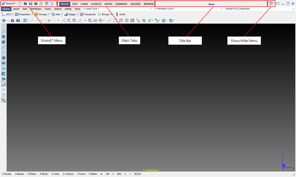
The main tabs are briefly described below:
-
The model is displayed and manipulated graphically in this tab.
-
Provides a text-based view of the finite element model whereby data such as node coordinates, element connectivity, and so on, are displayed in a grid, similarly to a spreadsheet. Data can be viewed, added, edited, copied, pasted and printed.
-
Load and freedom cases, including combination cases, influence case and envelope cases, are defined and managed in this tab.
-
Provides editing and viewing functionality for various types of supporting data typically used in a Strand7 model. These include tables, plies, laminates, creep data, reinforced concrete layouts, load path templates and cavity layouts.
-
Provides a notepad-style control that offers the possibility of writing notes to be stored with the model, as well as the definition of a title block to be displayed on printed pages.
-
Four sub-tabs are available to produce summaries of the finite element model. These are useful for model checking and for reporting and Quality Assurance purposes.
-
Provides access to all the solvers and the parameters required to run them. In post-processing mode this tab is hidden.
-
Provides a graphical tool to find and open Strand7 models, similarly to browse functionality offered in some image processing applications.
-
This tab becomes available in post-processing mode. It provides access to the raw numerical result data that is used in the production of contour plots and deformed displays.
The often-used icons are as follows:
-

Creates a new Strand7 model file. See Strand7 Menu: New.
-

Opens the File Open dialog to select and open an existing Strand7 model file. See Strand7 Menu: Open.
-

Saves the Strand7 model file. See Strand7 Menu: Saving.
-
Enables the opening of a results file, setting the model window into post-processing mode. If a result file is open, clicking the icon closes the result file, setting the model window back into pre-processing mode. See Strand7 Menu: Results Open/Close.
-

Opens the Open File dialog to select and open a log file. Log files are generated by the solver and by operations including import, export and automeshing. See View Log File: Log File Viewer.
-

Enables the formatting of floating point numbers (setting Fixed, Scientific, Engineering or Auto, amongst other options). The floating point format can be set differently for pre-processing and post-processing. See View Settings: Pre Numbers Tab and View Settings: Post Numbers Tab.
-

Switches to print-preview mode. This is available in The VISUAL Tab for print-previewing graphics, as well as other tabs such as The TEXT Tab and The SUMMARY Tab for print-previewing text-based data, and in tabs such as LAYOUTS: Tables for print-previewing graphs. See Strand7 Menu: Print Preview.
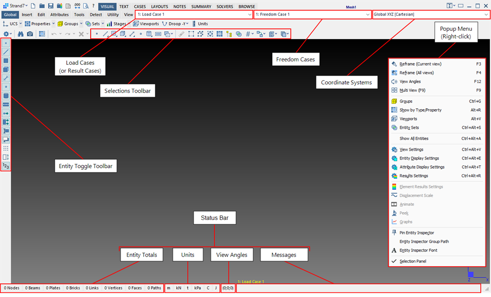
The image below identifies some of the main components of the VISUAL tab together with the components of the Status Bar. These are further described in the Definitions section below.
Selection Toolbar
The selection of entities in Strand7 is a frequently required operation. Entities need to be selected for a variety of reasons. Strand7 offers a suite of useful selection tools accessible via icons on the selection toolbar illustrated below.
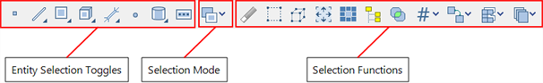
The icons on the left of the toolbar are the Selection Panel: Selection Entities and Mode. These are used for choosing the entity types to be selected by a given selection operation, and for setting how the selection state of an entity changes when it is selected (selection states can be set, cleared or toggled). The icons on the right of the toolbar are the Selection Panel: Selection Functions. These provide different selection tools (i.e., different ways to select), with each tool designed for a particular purpose.
Definitions
Familiarity with the following definitions will enable more efficient communication of Strand7 features and concepts between Strand7 users. It will also be useful for reading Strand7 documentation.
Attributes
Attributes are characteristics assigned to entities. For example, a Node Force is an attribute of a node. It describes a value of force assigned to a particular node. Similarly, a Plate Pressure is an attribute of a plate element.
Coordinate Systems
Once created, coordinate systems are accessible from the dropdown list. The Global XYZ [Cartesian] system is always available. See Global: User Coordinate System (UCS)
Entities
Entities are the main building blocks of a Strand7 finite element model. These include Nodes, Elements (i.e., beams, plates and brick elements), Links (e.g., rigid link), Paths, Vertices and Faces (geometry).
Entity Toggle Toolbar
The toolbar contains icons to quickly show or hide entities and attributes (i.e., toggle their visibility state). The toolbar is docked on the left side of the model window by default, but its position can be changed to dock right, top or bottom of the model window. See Strand7 Layout: Entity Toggle Toolbar.
Entity Totals
The total number of each of the main entities (e.g., nodes) is given in this area of the status bar. Additional information about each entity type can be obtained by clicking the corresponding cell on the status bar. See Strand7 Layout: Status Bar Popups.
Freedom Cases
The dropdown list selects the currently active freedom case. A freedom case groups together a set of freedom attributes (such as nodal restraints and element supports) which act together on a model. See CASES: Freedom Cases.
Load Cases/Result Cases
The dropdown list selects the currently active load case (in pre-processing mode) or the currently active result case (in post-processing mode when a results file is open). A load case groups together a set of load attributes that act simultaneously on a model. See CASES: Load Cases.
Model
The model is the Strand7 representation of the engineering structure being simulated or analysed. A model consists of entities, attributes, load and freedom cases, amongst other data types. A Strand7 model file has the extension ".ST7".
Model Window
The model window is shown above. It is the workspace associated with each open model (or file) providing access to graphical and text-based data representing the model.
Pre-processing Mode
When a result file is not open, and therefore the model may be modified or edited, Strand7 is in pre-processing mode.
Post-processing Mode
When a result file is open for results investigation, e.g., to display stress contours, Strand7 is in post-processing mode.
Popup Menu
A popup menu can be accessed by right-clicking the tabs area of the VISUAL tab. The menu includes frequently used commands for shortcut purposes. Strand7 can also be configured in Preferences: Other to open the popup menu by right-clicking anywhere in the graphical area of the VISUAL tab. See Strand7 Layout: Popup Menu.
Status Bar
The status bar gives live information about the model including entity totals, viewing angles and other context specific information. It also shows how many of each entity type are currently selected - selected counts are shown in red, in square brackets. The status bar reverts to a progress bar during long operations. Most of the items in the status bar respond to mouse clicks to provide additional information or functionality. See Strand7 Layout: Status Bar Popups.
Title Bar
The model file name is displayed in the title bar. A file explorer window can be quickly and easily opened at the location of the model file by right-clicking the title bar and selecting the popup menu function Open file location.
Units
This area of the status bar displays the units of length, force, mass, pressure/stress, temperature and energy used by the model. Units can be changed in pre-processing mode by clicking any of the units cells in the status bar.
View Angles
This field displays the current viewing angles. The viewing angles can be changed by clicking this cell of the status bar to bring up the View: View Angles dialog. By right-clicking this cell, a popup menu provides options for quickly setting the view to one of a number of pre-defined angles and orientations, amongst other view manipulation functions.
More details are described in the following topics:
See Also